
ASLC Load Bank Testing System for Standard Industrial Generator Wet Stacking Prevention
Load Bank Testing / ASLC System / Industrial Generator Adaptation
ASLC Load Bank Testing System for Standard Industrial Generator Wet Stacking Prevention
An ASLC load bank testing system connects a standard industrial diesel generator with a controllable load bank. It provides automatic supplemental loading, routine exercising, and wet stacking prevention without changing the generator core package.
Low-Load Operation Creates the Wet Stacking Condition
Diesel generator wet stacking is the accumulation of unburned fuel, soot, and exhaust residue caused by incomplete combustion during long low-load operation.
Combustion Boundary
The engine may run normally, but cylinder temperature and exhaust gas temperature remain below the range needed for complete fuel burn. The result is wet carbon residue in the exhaust manifold, turbocharger, and aftertreatment path.
Site Conditions
- Standby gensets running routine self-tests with little building load.
- Data centers, hospitals, and financial facilities where real load may stay far below generator rating.
- Oversized generator sets selected for future expansion, N+1 redundancy, or motor-starting margin.
- Long idle periods, light-load monthly tests, and operation below manufacturer-recommended load range.
ASLC Adapts Standard Industrial Generators for Automatic Supplemental Loading
High-end industrial and data-center generator packages may include automatic load correction, scheduled exercising, and self-test functions. An ASLC load bank testing system adds similar operating logic by connecting an external load bank with the generator control loop.
System Function
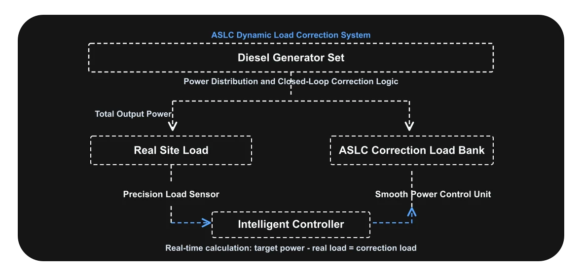
ASLC continuously measures the real terminal load. If the site load stays below the configured threshold for a defined time, the controller commands the load bank to add corrective kW until the generator returns to the target operating band.
Load Bank Options
- Air-cooled resistive load bank for simple dry heat dissipation.
- Liquid-cooled load bank for high-power sites with limited ventilation.
- Regenerative load bank where recovered electrical energy can be reused or fed back according to site rules.
- Mobile load bank package for periodic service and sites without fixed installation space.
Two Operating Modes in One Load Bank Asset
The same ASLC-capable load bank can support offline acceptance testing and online supplemental loading. This improves asset utilization and reduces the need for separate fixed anti-wet-stacking equipment.
Offline Load Bank Test
The load bank operates as a conventional test load. It supports staged loading such as 25%, 50%, 75%, and 100% for acceptance testing, periodic maintenance, exhaust temperature recovery, and carbon burn-off.
Online Load Correction
The load bank is paralleled with the generator system. Sensors sample real load, and the controller adds only the missing corrective load required to keep the engine in a healthier combustion zone.
Closed-Loop Control Logic
ASLC is not a fixed dummy load. It is a closed-loop correction system. The controller calculates the difference between target generator loading and real site demand, then adjusts the load bank output.
Engineering Safeguards for Live Generator Systems
In online correction mode, the load bank must never compete with the protected facility load. Control priority, fast unloading, and electrical protection are the main design points.
Real Load Priority
The facility load has first priority. If ATS transfer, motor starting, UPS recharge, or data center IT load causes a sudden kW increase, ASLC removes correction load before the generator reaches overload trip limits.
Smooth Power Control
SCR or high-frequency solid-state regulation allows fine load trimming. The generator sees a controlled load ramp instead of a large mechanical step, reducing voltage and frequency disturbance.
Electrical Protection
Protection logic should include overcurrent, overtemperature, fan or pump fault, phase loss, abnormal frequency, emergency stop, communication loss, and load bank branch fault isolation.
Data Reporting
Daily operating curves help confirm whether the engine has spent enough time in a proper load band. Reports can support preventive maintenance and engine health assessment.
Conventional Service Still Has a Place
For sites without space or budget for a fixed system, mobile load bank testing remains a practical maintenance method. Service teams connect a trailer or truck-mounted load bank, load the generator in stages, and verify engine response under controlled conditions.
| Periodic Test Load | Typical service sequences use 25%, 50%, 75%, and 100% steps. High-load running may last 1-4 hours depending on engine condition and service procedure. |
|---|---|
| Observed Parameters | Voltage, frequency, current balance, oil pressure, coolant temperature, exhaust temperature, smoke condition, and load acceptance. |
| Maintenance Value | Staged load testing burns off deposits, confirms standby performance, and provides a documented health report. |
| Limit | Periodic service does not protect the generator during every low-load operating hour. ASLC is used when continuous or automatic correction is required. |
Generator Compatibility Parameters
ASLC design should start from generator and site data, not from a fixed load bank catalog size. The controller, power stage, cooling method, and connection method must match the actual electrical system.
| Generator Rating | Standby or prime rating, kW/kVA, voltage class, frequency, phase, power factor, alternator capacity, and overload margin. |
|---|---|
| Low-Load Rule | OEM minimum load recommendation, site low-load threshold, correction delay time, target load band, and maximum allowed supplemental load. |
| Signal Interface | CT/PT input, power meter signal, genset controller data, dry contacts, Modbus RTU, Modbus TCP, RS485, or Ethernet integration. |
| Load Bank Type | Resistive, resistive/reactive, liquid-cooled, air-cooled, or regenerative configuration according to power rating, installation space, heat rejection path, and energy reuse requirement. |
| Installation Boundary | Switchgear position, breaker coordination, cable route, ventilation or coolant connection, emergency stop circuit, and service clearance. |
Engineering Data Required Before ASLC Load Bank System Design
For a reliable wet stacking control design, confirm generator rating, minimum load rule, site load profile, available switchgear connection point, control signal protocol, cooling condition, and required reporting format.